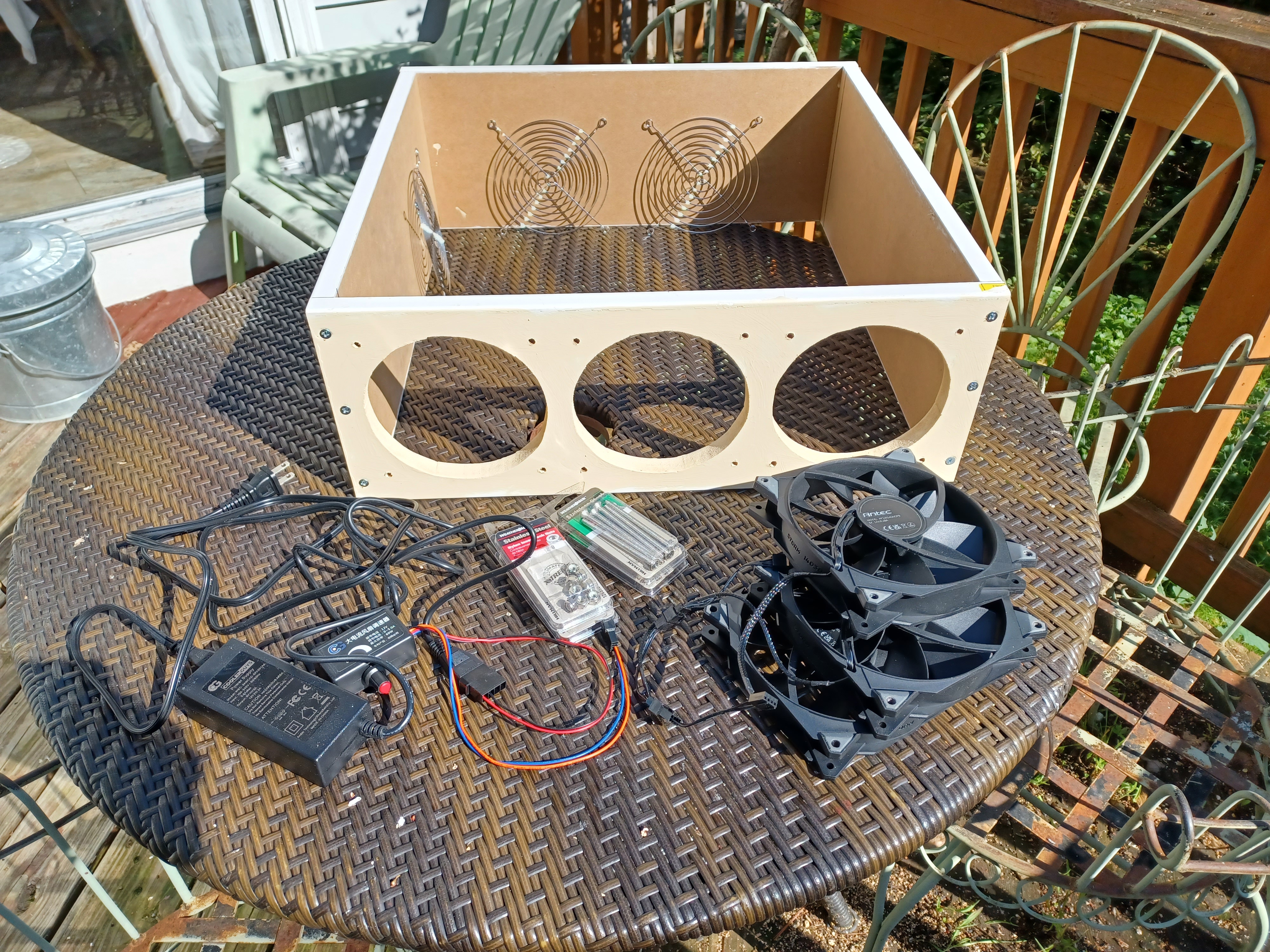
The parts.
Online examples I found are made of foam board. I wanted something sturdier, that will last for decades, with only the occasional filter change.* I decided on wood, but at the store, I had to choose between rough pine with massive splinters and MDF (medium density fiberboard, a stronger and denser version of particle board). MDF it was.
* Furnace filters are changed every three months, but those filter all the air (and all the airborne dust) in a house. This box is only filtering one room, with the dust divided between two filters. I expect you can space out the filter changes by well over a year. If needed, you might try vacuuming animal hair off of them, while the box is not running. Remember, the filters should be MERV13 or higher!
A 20" filter isn't actually 20", and I'm glad I was paranoid enough to measure it myself.
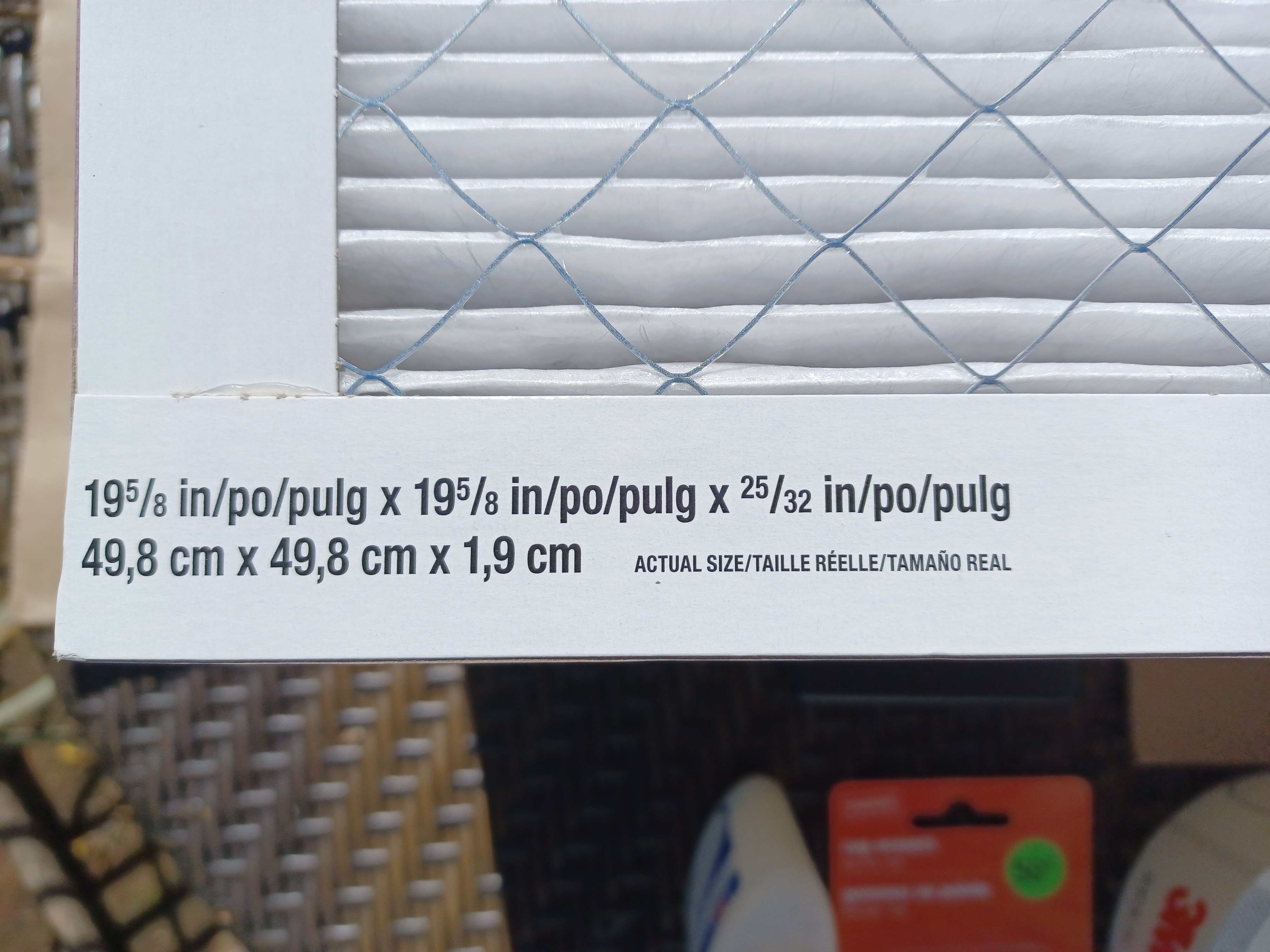
Oh look, it says so right there (I discovered later)!
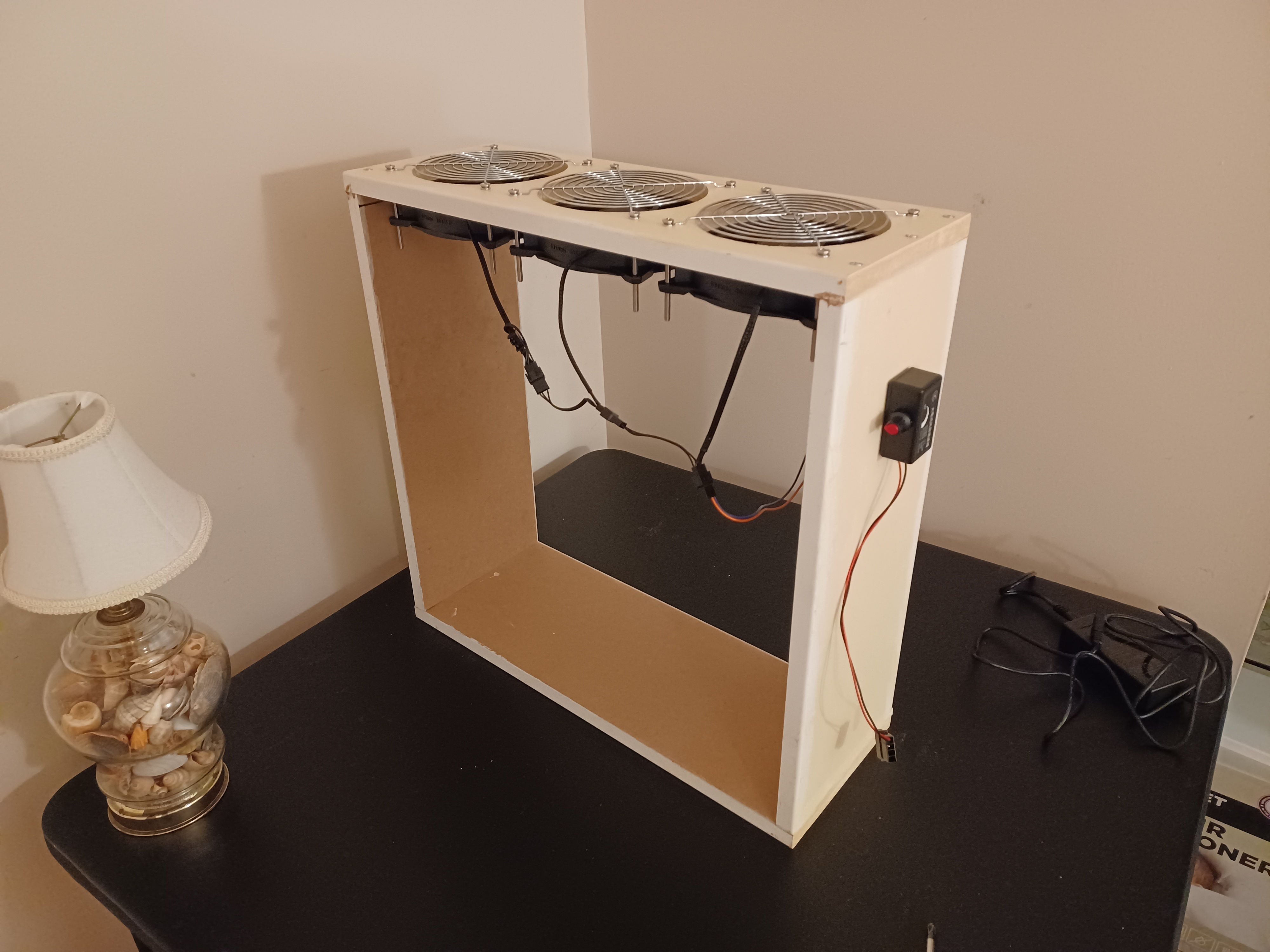
When measuring and cutting, I matched the external box dimension to the filters. The filters should adjoin the outside of the box, not slide into it, for at least three good reasons. (Ask me in comments, if they're not apparent.) My work bench is the lid of my chest freezer, so a friend with a workshop helped me with cutting the big holes: 138mm (5.433") across, to match the inside diameter of the 140mm fans. I used wood glue and three screws per side, drilling pilot holes and turning the screws with a regular screwdriver (pushing a little the whole time). MDF is not as firm as decent wood (nor is pine): I needed the box sturdy, and I didn't want to risk stripping the screw holes with power tools. The top and bottom are the longer pieces because the screws have to be vertical: Horizontal screws would have poked out into the vent holes. I painted the exposed parts of the boards before assembling them, and gave the rough, unprimed surfaces (including the vent holes) a much needed second coat afterward. That also sealed up the joints better against drink splashes and dust.
The fans.
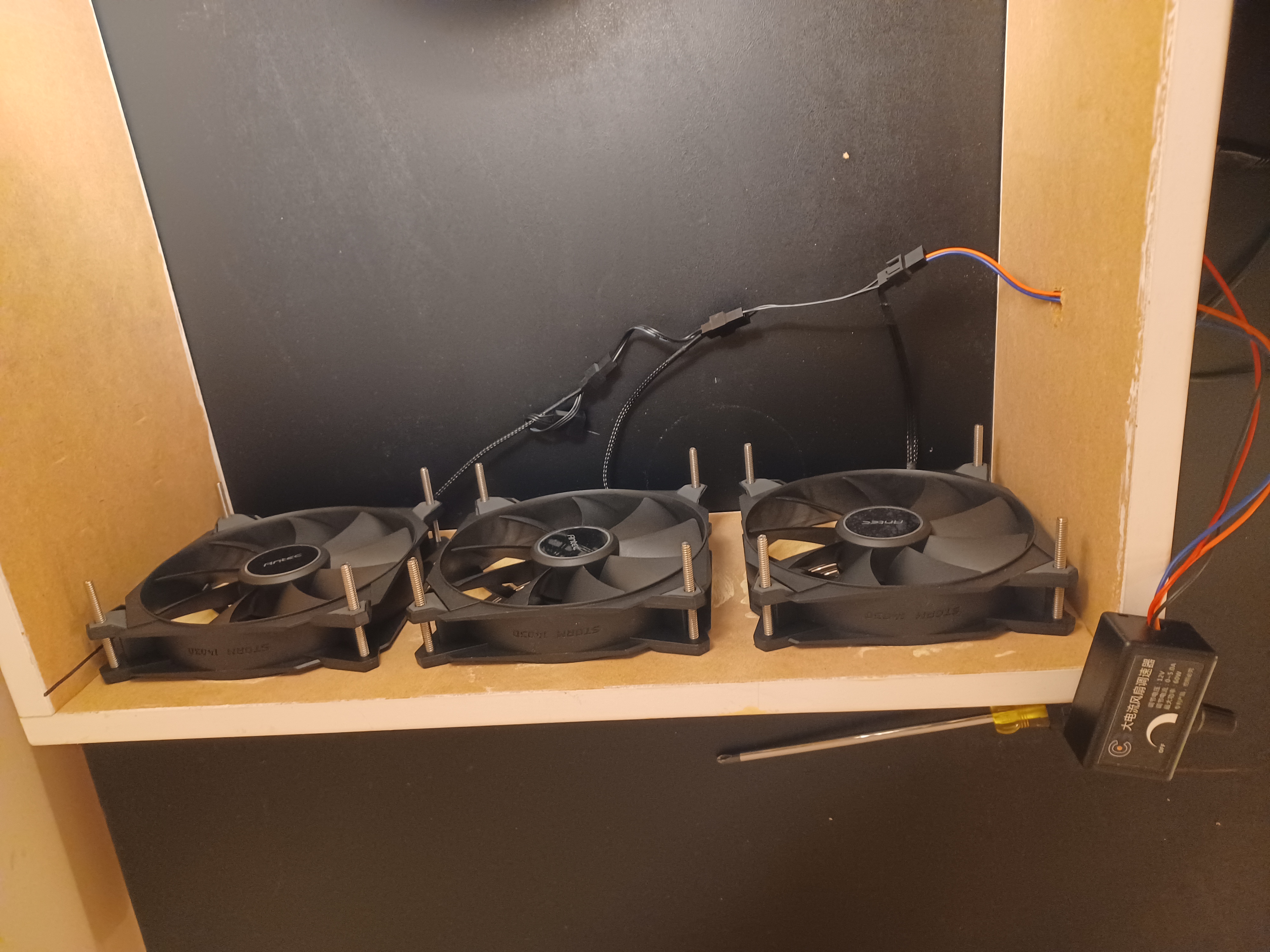
I'll give links for convenience. (No affiliate links; Amazon is evil.) I got a three-pack of 140mm Antec Storm T3 fans. They're powered by a 2 amp power supply. The three fans together draw 1 amp, so I didn't want just a 1 amp power supply: I've read that running a power supply at over 75% of its capacity for long periods can be bad for it. I connected this to the fans with a fan controller knob. Theoretically, this would provide an adjustable fan speed, but this controller whines annoyingly if you turn it down to partial power. I don't care, though: It's a solution for bridging the big (Molex) power output to the small (PWM) fan power input, and works fine as an on/off switch (if you can deal with half a second of whining on the way).
You might have noticed that the fans are not secured onto the screws with nuts! I did in fact buy lock nuts. By good or bad luck, the 10-24 x 3" screws couldn't quite slide through the anchor holes on the fans... But they could thread through! This was a long, slow, careful process that would never have worked if I hadn't been absurdly, meticulously precise when drilling the holes for these screws in the MDF board. I do not recommend attempting it, and I wouldn't have planned it that way myself. As it is, these fans are screwed on tightly, no nuts needed. I could have gotten away with 2" screws, had I known not to leave room for the nuts. Shorter, narrower screws going only through the top anchors would have been cheaper and way easier, and also allowed more error tolerance.
I double- and triple-checked the fan direction as I went, to make sure they blew out, not in.
The grills.
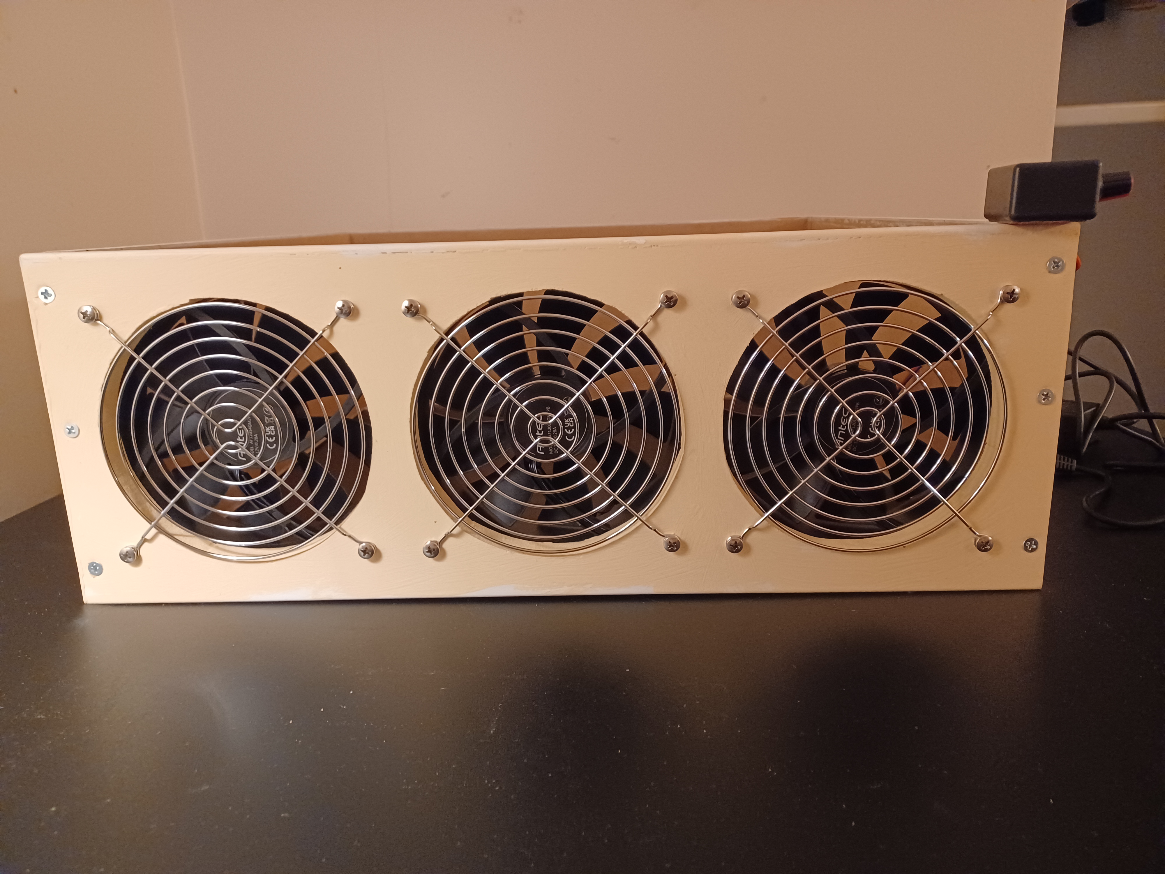
I got two two packs of fan grills to keep foreign objects from falling in and smashing the running fan blades. Sixty years from now, I'll think of a use for the one leftover grill. And I will know exactly where it is.
The assembled hardware.
The electronics are now assembled. I didn't need a splitter to power the three fans: They chain together. I made a hole in the side for the wires, before assembling the box. (If you're following this story as directions, and didn't already do that... Whoops!) It needed to be just big enough to pass the small PWM jack (power output) from the knob. The knob's case is self-adhesive. I pushed the wires to the bottom of their hole, and covered the rest of the hole with the knob case. In a project full of "I don't know what I'm doing" moments, that at least made me feel clever. The power hole still left a tiny gap for unwanted airflow around the wires, so I stuffed an earplug vertically into it.

Wait a minute...
This doesn't look good. Constant weight hanging from those two tiny wires might stress them until the slightest yank ruins the whole thing.

Fixed!
Taping up the junction sufficed. (Just don't leave the power cord where it might be tripped over!) After yet another check that the electronics worked, I carefully aligned the filters with the box as I taped them. The filters have arrows indicating which way air is supposed to flow through them: Those arrows point in, toward the box.

Done!
And there it is: A state of the art, 12 core, 4.8GHz, custom framed Corsi-Rosenthal box.